- Visibility 148 Views
- Downloads 248 Downloads
- DOI 10.18231/j.aprd.2021.028
-
CrossMark

Biomechanics in dental implants
Introduction
Dental biomechanics is defined as the relationship between the biologic behavior of oral structures and the physical influence of a dental restoration [GPT-9].
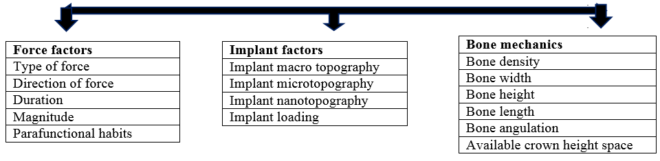
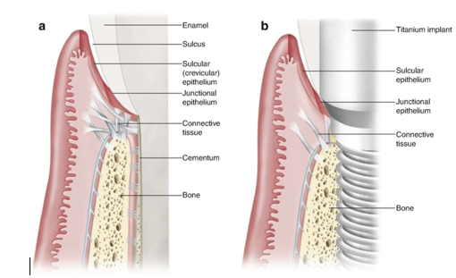
Biomechanics comprises of all kinds of interactions between tissues of the body and forces acting on them and response of the tissues to the applied loads.[1] The loads acting on the dental implant are transferred to the surrounding biological tissues. Implant biomechanics can be reactive or therapeutic in nature. It deals with biomechanical factors that are of destructive nature to the implants and the clinical process of altering each biomechanical factor to reduce the cumulative response causing implant overload.[2] The biomechanics acting on a natural tooth and implant differ due to various reasons. ([Table 1], [Figure 2])
Implant biomechanics can be explained under following heads-
Discussion
Forces acting on the Implant
Forces applied to the implant may be assessed in type, direction, magnitude, duration and presence of any parafunctional forces. From the simple mathematical equation of Stress = Force ÷ Surface area, it can be observed that, to decrease the stress, the functional surface area should increase or the force should decrease.
Cowin in 1989 suggested that cortical bone is strongest in compression and also can be well tolerated by the bone-implant system.[3] Shear and tensile forces, being angular in nature, direct stresses over the crestal bone and bone-implant interface, which can be detrimental to implant in the long run. A 30-degree angled load will increase the overall stress by 50% compared to the load applied along the long axis. [4]
The magnitude of forces applied varies based on the anatomical region, age, gender and state of dentition. Craig in 1980 described that the magnitude of bite force is greater in the molar region (200 lb), less in the canine area (100 lb), least in the anterior incisor region (25 to 35 lb) and increases upto 1000lb in the presence of parafunctional habits such as bruxism, clenching and tongue thrusting.[5] These parafunctional habits increase the duration of bite forces, that exceed the endurance limit of the implant components and can lead to screw loosening or fatigue failure. [6]
Implant related factors
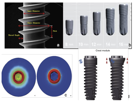
Implant design should maximize implant surface area and create a better spreading of stress and primary stability. [7]([Figure 3])
Implant macro design
Thread shape and stress distribution: The thread shapes in dental implants are developed for easier insertion and force transmission to surrounding bone. Using a linear motion through rotation, threaded implants are inserted into the osteotomy site. Thread shapes available for screw-retained implants include square shape, V-shape, buttress and reverse buttress threads, which are defined by the thread thickness and face angle. Implant threads increase surface contact area and favourable forces while reducing adverse stimuli.
Using Finite Element Analysis, Chia Ching Lee and his colleagues evaluated the effects of implant threads (symmetrical, square and buttressed) on the contact area and stress distribution of marginal bone. [8] Among the three thread shapes, the contact area with square thread was highest and the force dissipation around marginal bone was least. In a study by Eraslanet al, performed with four different thread forms under a static axial load of 100 N, it was observed that maximum stress was concentrated at the cervical cortical regions around the first thread and the stress value was lowest in the square thread type. [9]
Thread pitch and lead
Pitch is an important geometric factor that determines the bone-to-implant contact (BIC) and the biomechanical load distribution. Thread pitch is defined as the distance between two neighbouring threads, measured on the same side of the axis, It also refers to the number of threads per unit length. implants having smaller pitch indicates more threads, leading to greater surface area.[10] In a histological analytical study conducted by Paolo Trisi et al on sheep bone, it was observed that large threaded implants showed significantly higher %BIC and %BV than small threaded implants in low-density bone and statistically higher secondary stability in cancellous and cortical bones. [11]
Lead is the distance within the same thread before and after one complete rotation in the axial direction. That is, for single, double, and triple-threaded implants, lead increases by one, two, and three times the pitch respectively. Lead indicates the distance that an implant would move after one turn and it plays an important role on determining the speed of implant insertion. A FEA conducted by Yoko Yamaguchi suggested that, to achieve good primary stability, increasing the thread length and reducing the pitch/lead and lead angle to that of a single-threaded implant is considered more effective versus using a double-threaded implant. [12]
Thread depth and width
According to Misch, thread depth is the distance from the outermost tip to the innermost body of the thread.[7] He defines thread width as the distance between the superior most and inferior-most tip of a single thread measured axially. Shallow thread depth implants, allow an easy implant placement, especially in the high-density bone. Implants with deep thread depth can be used in low density bone, to increase the functional surface area. A study conducted by Sun-Young Lee et al to evaluate the effect of thread depth on primary stability in low density bone concluded that implant with deep threads provide better mechanical stability in areas of low density bone.[8]
Various implant systems are available using progressive threads; for example, Ankylos (Dentsply Friadent, Mannheim, Germany). In this thread form, thread depth gradually decreases from the apical end to the coronal neck of the implant. [13]
Implant length and width
An increase in implant length has a benefit for initial stability as overall total surface area increases. It provides resistance to torque or shear forces and also achieves bicortical stabilization.
Wider root form implants have a greater area of bone contact and help in dissipation of forces over a wider area.
Each 0.25 mm increase in implant diameter may increase the overall surface area 5% to 10% in a cylinder implant body.
Hamidreiza in his study evaluated the influence of mechanical characteristics of the implant on primary stability in different bone types, based on resonance frequency analysis (RFA). He concluded that in cases with D1 type of bone, implant length did not have significant increase in primary stability. But in cases with low density bone, increasing implant width and length helps achieve primary stability. The greater diameter not only decreases stress but also decreases the likelihood of implant fracture. [14]
Crest module considerations
The crest module of an implant body is the transosteal region, the crest module of the implant has a surgical influence, a biological width influence, a loading profile consideration (characterized as a region of highly concentrated mechanical stress).[15] The crest module seals completely the osteotomy, providing a barrier and deterrent for the ingress of bacteria or fibrous tissue during initial healing. ([Table 2])
Apical design consideration: round cross section implants donot resist torsional shear forces when abutment screws are tightened. Hence, anti-rotational features are added.
Implant Microtopography
Alteration of microtopography of implant is done using sandblasting, acid etching, grit blasting which create imperfection along the machined surface, thusincreasing surface area and attracting osteogenic cells to cause bone formation.
Implant Nano-topography
Comprises of Cell-implant interaction at cellular and protein level. It includes anodic oxidation, laser ablation, TiO2 blasted implants. These implants are proven to prevent crestal bone loss and increase soft tissue seal. [16], [17]
Loading protocols
Misch in 1980 proposed that gradual increase in occlusal load separated by a time interval to allow bone to accommodate. [7]
Softer bone— increase in progressive loading period.
Protocol includes time, diet, occlusal consideration, prosthesis design. [18]
Bone factors: [7], [19] (Fig 3)
Density of bone
Bone constitute the ideal case for implant placement.
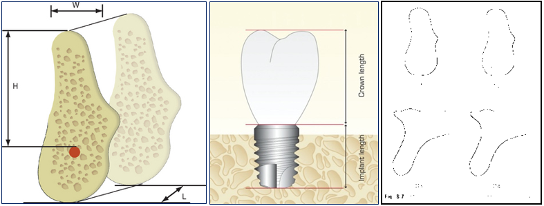
Available bone height: Measured from crest of ridge to opposing anatomical landmark. Related to density of bone.High density bones- shorter implants can be accommodated.Low density bones- longer implants needed.
Available bone width: Wider ridges allow placement of wider implants, thus increasing surface area and force dissipation.
Available bone length: Length minimum should be 8mm
Bone angulation: Ideally, bone is perpendicular to the plane of occlusion,aligned with the forces of occlusion and is parallel to the long axis of prosthodontic restoration. Bone angulation should be less than 30o. [20]
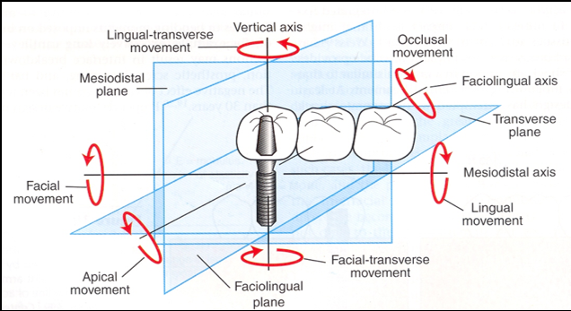
Clinical moment arms
A total of six moments (rotations) may develop about the three clinical coordinate axes previously described:occluso-apical, labiolingual and mesiodistal axes( Such moment loads induce microrotations and stress concentrations at the crest of the alveolar ridge at the implant-tissue interface, which lead to crestal bone loss.
Three clinical moment arms exist in implant dentistry
Occlusal height.
Cantilever length.
Occlusal width.
Minimization of each of these moment arms is necessary to prevent unretained restorations, fracture of components, crestal bone loss, or complete implant system failure.
Occlusal height
Directed along facio-lingual axis-Working or balancing occlusal contacts.
Mesio-distal axis- tongue thrusts or peri-oral musculature.
Vertical axis- no moment load induced.
Cantilever length:[21]
Vertical axis- large moment arms.
Lingual force component- twisting moment on implant neck axis.
Force directly on implant- no moment loads, torque or rotation induced.
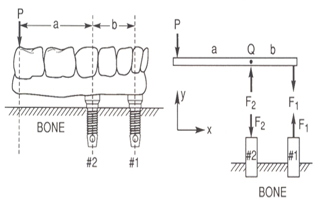
Considerations for Cantilevered prosthesis ([Figure 6])
Clinical experiences suggest that the distal cantilever should not extend 2.5 times the A-P distance under ideal conditions [to achieve stabilizing effect].
Patients with parafunction not to be restored with cantilever - More offset loads are applied.
Tapered arch forms offer larger AP distance than square arch forms. ([Table 3])
|
Natural tooth |
Implant |
|
Has periodontal ligament, shock absorption capacity |
‘Functional ankylosis’ to bone |
|
Shows flexion |
Is rigid or stiff |
|
Stress is distributed evenly to surrounding bone |
Stress concentrates over crestal bone |
|
Proprioception of about 20 µm |
Proprioception of 48-64 µm and around 106 µm in case of implant over dentures |
|
Apical intrusion by about 28 µm and lateral movement by around50-108 µm |
Apical movement observed is around 10-30 µm |
|
Larger crest module diameter |
Increases surface area |
|
|
Decrease stress at the crestal region |
|
|
Increases the platform of the abutment connection |
|
|
Reduced stress to the abutment screw during lateral loading |
|
Smooth collar |
Reduction of plaque accumulation and improved hygiene. |
|
Extended smooth collar |
Shear load- crestal bone loss |
|
Load applied |
Forces acting |
|
100 N force on implant |
No moment loads, torque or rotation |
|
Load on cantilever at 1 cm distance |
100Ncm load |
|
At 2 cm distance |
200Ncm load |
|
At 3 cm distance |
300Ncm load |
|
Implants tightened with 30Ncm torque |
|
Bone density |
Implant consideration |
Rationale |
|
D1, D2 (High/ medium density bone) |
Shorter implants Narrow implants Shallow thread depth implants Implant with lesser threads Ideal crown height space |
More intimate contact of bone with implant surface Lesser moment loads acting on implant Forces dissipated along long axis of implant Lesser healing time FP1, FP2 prosthesis Cantilevered prosthesis can be considered |
|
D3, D4 (Low density bone) |
Longer implants Wider implant Deep thread implants Lesser pitch implants Coated implants Increased crown height space |
To achieve increased functional surface area More clinical moment arms acting, more rotation and torquing forces Shear and tensile forces present RP4, RP5 prosthesis |
Occlusal width
Wide occlusal table- Facio-lingual tipping (rotation) increased.
Narrow table- provides more centric contacts.
Conclusion
The success of the therapy in Oral implantology is dependant equally on principles of biomechanics and strict clinical protocol adherence. Failures result if either of these are not followed or taken into consideration. Biomechanics are involved in the conception of a new implant prototype (determining the need for certain modifications to existing designs), producing and testing (in vitro and in vivo) of the implant and all the clinical stages (planning, insertion, loading, maintenance).
Although modern day implants are versatile, present high success rates, increased patient acceptance and comfort, the scope still exists for improvement and research and d evelopment should be directed towards it.
Conflict of Interest
The authors declare that there are no conflicts of interest in this paper.
Source of Funding
None.
References
- C E Misch, M W Bidez, CE Misch. A scientific rationale for dental implant design. Contemporary implant dentistry. 2nd Edn. 1999. [Google Scholar]
- C E Misch. Early crestal bone loss etiology and its effect on treatment planning for implants. D 1995. [Google Scholar]
- S C Cowin. Bone mechanics, Boca Raton, Fla. 1989. [Google Scholar]
- C E Misch, MW Bidez. MW Implant-protected occlusion: A biomechanical rationale. Compendium 1994. [Google Scholar]
- I Scott, M M Ash. A six channel intra-oral transmitter for measuring occlusal forces. J Prosthet Dent 1966. [Google Scholar]
- C E Misch, J B Suzuki, F M Misch-Dietsh, M W Bidez. A positive correlation between occlusal trauma and peri- implant bone loss: Literature support. Implant Dent 2005. [Google Scholar] [Crossref]
- C E Misch, T Strong, M W Bidez, CE Misch. Scientific rationale for dental implant design. Contemporary Implant Dentistry. 3rd Edn. . [Google Scholar]
- CC Lee, SC Lin, MJ Kang, SW Wu, PY Fu. Effects of implant threads on the contact area and stress distribution of marginal bone. J Dent Sci 2010. [Google Scholar]
- O Eraslan, O Inan. The effect of thread design on stress distribution in a solid screw implant: A 3D finite element analysis. Clin Oral Investig 2010. [Google Scholar] [Crossref]
- C J Ivanoff, K Gröndahl, L Sennerby, C Bergström, U Lekholm. Influence of variations in implant diameters: A 3-5 year retrospective clinical report. Int J Oral Maxillofac Implants 1999. [Google Scholar]
- T Paolo, T Marzio, T Domenico. High versus low implant insertion torque. A histological, histomorphometric, Biomechanical study in the sheep mandible. Int J Maxillofac Implant 2011. [Google Scholar]
- Yamaguchi. Effect of implant design on primary stability using torque time curves in artificial bone. International Journal of Implant Dentistry 2015. [Google Scholar] [Crossref]
- H Abuhussein, G Pagni, A Rebaudi, H L Wang. The effect of thread pattern upon implant osseointegration. Clin Oral Implants Res 2010. [Google Scholar] [Crossref]
- B Hamidreiza. The Effect of Implant Length and Diameter on the Primary Stability in Different Bone Types. J Dent (Tehran) 2013. [Google Scholar]
- S Hansson. The implant neck: Smooth or provided with retention elements. A biomechanical approach. Clin Oral Implants Res 1999. [Google Scholar]
- B C Muddugangadhar, G S Amarnath, S Tripathi, S D Divya. Biomaterials for Dental Implants: An Overview. Int J Oral Implantol Clin Res 2011. [Google Scholar]
- A Wennerberg, T Albrektsson. On implant surfaces: A review of current knowledge and opinions. Int J Oral Maxillofac Implants 2010. [Google Scholar]
- S Szmukler-Moncler, H Salama, Y Reingewirtz, J H Dubruille. The timing of loading and the effect of micro- motion on the dental implant-bone interface: A review of the experimental literature. J Biomed Mater Res 1998. [Google Scholar]
- C E Misch. Density of bone: Effect on treatment plans, surgical approach, healing, and progressive loading. Int J Oral Implant 1990. [Google Scholar]
- M W Bidez, C E Misch. Issues in bone mechanics related to oral implants. Implant Dent 1992. [Google Scholar] [Crossref]
- A Sertgoz, S Guvener. Finite element analysis of the effect of cantilever and implant length on stress distribution on implant supported prosthesis. J Prosthet Dent 1996. [Google Scholar]
- Introduction
- Discussion
- Forces acting on the Implant
- Implant related factors
- Implant macro design
- Thread pitch and lead
- Thread depth and width
- Implant length and width
- Crest module considerations
- Implant Microtopography
- Implant Nano-topography
- Loading protocols
- Bone factors: [7], [19] (Fig 3)
- Clinical moment arms
- Conclusion
- Conflict of Interest
- Source of Funding